
Published · Kuohai Editorial
What does a high-level alarm tell you?
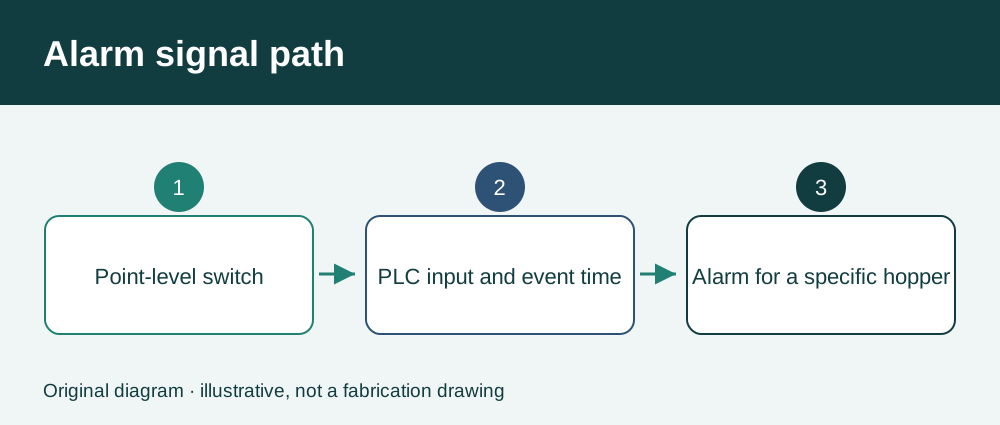
A high-level alarm identifies a change at a particular sensing point. A rotary paddle switch, for example, changes state when material prevents the paddle from turning. The switch provides a point indication at its mounting elevation. Establish which switch produced the alarm before drawing conclusions about the amount of dust in the hopper. A bin or drum level alarm can have a separate input and a separate response.
Compare the alarm with the discharge sequence
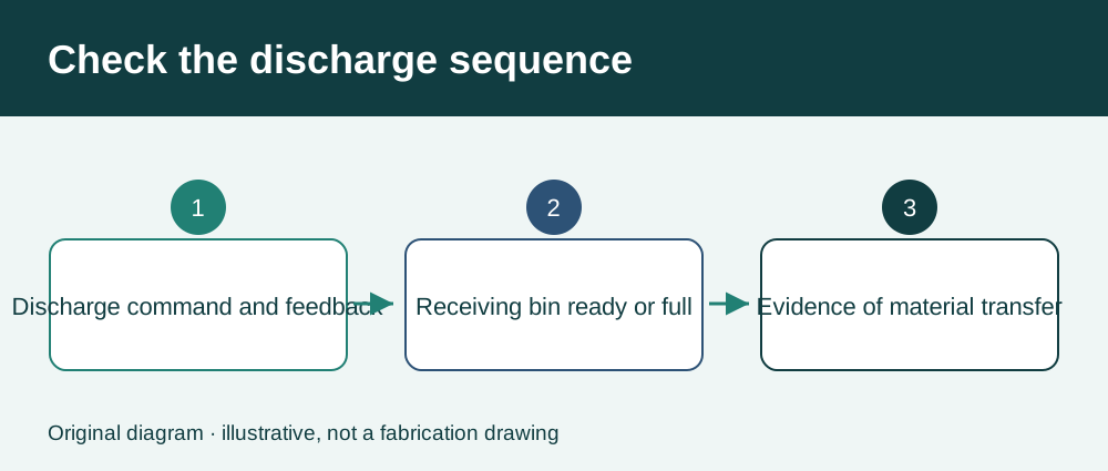
Start with the event time, the affected hopper and the last confirmed dust transfer. Compare the airlock or screw start command with actual run feedback, drive faults and the receiver’s ready or full status. If the run command was present but feedback dropped first, investigate the drive and its permissives. If the receiver went full first, trace how that signal affected the discharge sequence. Motor feedback alone cannot establish that material flowed.
Check the field device and the signal path
If the receiver had capacity and discharge was independently confirmed, inspect the switch signal path under the site’s approved procedure. Compare the local indication with the PLC input and historian. With the equipment isolated and a qualified person performing the work, check for deposits at the sensing point, an obstructed paddle or an intermittent connection. Record the installation height, device model and configured normal state so the next technician can reproduce the check.
Write an alarm response operators can follow
Name the hopper and switch on the alarm display. Keep the time of first alarm, return to normal and any recurring transitions. Document which equipment can inhibit discharge and what confirms a successful transfer. Have the controls and process owners agree on escalation and restart criteria, especially where several hoppers share one receiver.
FAQ: Does normal filter differential pressure rule out a high hopper level?
No. Filter differential pressure indicates resistance across the filter section. Use the level input and discharge evidence to investigate ash accumulation, even when filter differential pressure is near its usual operating range.
FAQ: Can we bypass the switch to keep the collector running?
Follow the site’s approved alarm and interlock procedure. If the input is unreliable, document the fault and obtain the responsible owner’s decision on the equipment’s safe operating state.
Technical sources and editorial note
Use the collector drawings, device manual and approved isolation procedure for field checks. The figures show generic signal relationships.
Related equipment: Pulse jet baghouse dust collectors · Dust collector filter bags
Use this guide to prepare for an equipment discussion. Confirm selection and operating requirements against your actual process and site conditions.